|
TYPE AB PULSE FORMING NETWORKS
METALLIZED MYLAR* CAPACITORS
|
| The data contained herein shows only a PARTIAL LISTING of items available for this product line and it gives only a CONDENSED VERSION of the applicable specifications and characteristics. Request our complete catalog for full information! |
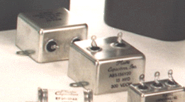 Type AB capacitors are designed with the requirements of MIL-C-18312 in mind, type CH-53 and CH-54, as an economical, non-QPL, substitute. Other styles, such as type CH-09 or CH-70, are available on special order. Type AB capacitors are metallized Mylar* elements hermetically sealed in a bathtub style container. The self-healing and cleaning characteristics make possible the smallest high quality capacitor for the given rating. Type AB capacitors are designed with the requirements of MIL-C-18312 in mind, type CH-53 and CH-54, as an economical, non-QPL, substitute. Other styles, such as type CH-09 or CH-70, are available on special order. Type AB capacitors are metallized Mylar* elements hermetically sealed in a bathtub style container. The self-healing and cleaning characteristics make possible the smallest high quality capacitor for the given rating.
Mylar* Film, one of the many dielectrics employed by us in the fabrication of the highest quality capacitors, offers particular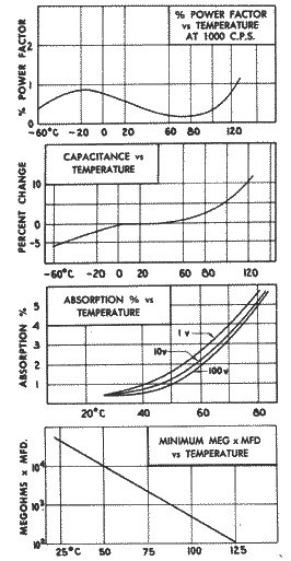 advantages not obtainable with other materials. Mylar* satisfies the requirements of high resistance, low absorption, excellent retrace and capacitance stability over a wide temperature range and high ambient operating conditions. advantages not obtainable with other materials. Mylar* satisfies the requirements of high resistance, low absorption, excellent retrace and capacitance stability over a wide temperature range and high ambient operating conditions.
Metallized Mylar* has several advantages that are outstanding. The self-healing characteristics are well-known and extend the useful life of the capacitor. The second, and most over-looked feature, is the possibility of making full use of the highest volts-per-mil rating of the film by eliminating all the weak dielectric areas. This results in extreme small size without sacrificing life, reliability and economy.
Wide Temperature Range: Operating and storage, minus 90°C to 125°C at full nameplate rating except all capacitors greater than 10 mfd. with a 200 volts nameplate rating should be de-rated to 150 volts in the temperature range of 100°C to 125°C. (Consult specific type listing for complete information)
Capacitance Tolerance standard is 20%. Also available are tolerances of 10%, 5%, 2% and 1%. Nominal values of capacitance of 1 mfd. or less are measured with 1000Hz applied to the bridge and 60Hz for nominal values greater than 1 mfd.
Insulation Resistance: At 25°C the RC exceeds 50,000 megohms, but need not exceed 100,000 megohms. Either terminal to case is in excess of 50,000 megohms. For other temperatures consult "Resistance vs. Temperature" curve for minimum RC, but need not exceed double the minimum value at any temperature.
Low Dielectric Absorption: Variable and a function of voltage applied and temperature. (See applicable curves) At room temperature, dielectric absorption is less than 0.3% when tested in the following manner: Short capacitor for two hours. Apply a stable charging voltage for one hour. Discharge the capacitor for 1/3 second. Periodically read recovery voltage until a maximum is reached. The voltmeter or electrometer should have a terminal resistance of 10¹¹ ohms or more. Percent absorption is defined by:
% absorption = max. recovery voltage x 100 / charge voltage
Ripple: The sum of the peak ripple voltage plus the DC voltage should not exceed the nameplate voltage. Listed below are acceptable peak to peak ripple voltages in percent of nameplate voltage ratings:
Frequency
Hz |
Peak to Peak
Ripple Voltage |
| 60 |
25% |
| 120 |
20% |
| 400 |
10% |
| 1000 |
8% |
Power Factor is less than 1% at 25°C. Power factor will be measured at 1000 Hertz for 1 mfd. or less capacitance and at 60 Hertz for nominal values greater than 1 mfd. (See typical curve of "Power Factor vs. Temperature"). Consult specific type listing for complete information.
Applications:
| Computer circuits |
Audio coupling |
Tuned filters |
Pulse forming networks |
| Energy storage |
Oscillator circuits |
Power supply filters |
Power factor correction |
| Arc and spark suppression |
Integrating circuits |
Audio and RF bypass |
Analog computers |
| Low and high pass filters |
Radio frequency coupling |
|
|
Container is hot-tinned steel or terne-plate, designed to withstand the 100 hour salt spray test of MIL-QQ-151A.
Terminals are solder lugs in a soldered compression seal brushing.
TEST CONDITIONS
Test Voltage: Terminal to terminal is 200% rated voltage for one minute without a permanent breakdown.
Terminal to case: With both terminals tied together, terminals to case test voltage is 200% rated voltage for two minutes. The test voltage shall be applied and removed through a resistance of not less than one ohm per volt applied and at room temperature.
Life Test will be conducted at 125°C with a test potential of 120% nameplate voltage applied for 250 hours. One failure of twelve so tested will be permitted. Failure is defined as a permanent short circuit, drop in capacitance of 5% or a change in insulation resistance to a value lower than the minimum RC indicated in the insulation resistance paragraph.
Temperature and Immersion cycling shall be conducted per requirements of MIL-C-25D.
Moisture Resistance shall be conducted per requirements of MIL-C-25D.
Corrosion or Salt Spray test shall be conducted according to the 100 hours requirement of MIL-QQ-151A.
Vibration and Shock test shall be performed per MIL-C-25D or MIL-E-5272 (any method).
Production Hermetic Seal Test is conducted by immersing the capacitors in silicone fluid at a temperature of 125°C for four minutes. There shall be no appearance of air escaping from the capacitor for the duration of the immersion.
Capacitance Tolerance shall be measured at 25°C ±5°C.
Humidity tests may be performed according to any method of MIL-C-25D, MIL-E-5272A OR MIL-E-6400.
How to Order: Check the listing for voltage and capacitance required and use indicated part number. Add suffix letter
x - for side mounted terminals
y - for top mounted terminals
z - for bottom mounted terminals
Add 20 for standard 20% tolerance, 10, 5, 2 or 1 for 10%, 5%, 2% or 1% tolerance.
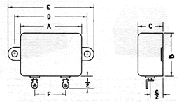
| Part Number |
CAP. MFD. |
Volts D.C. |
|
Case Size |
|
|
Part Number |
CAP. MFD. |
Volts D.C. |
|
Case Size |
|
| A |
B |
C |
A |
B |
C |
| AB2-504 |
0.5 |
200 |
1-1/8 |
1 |
13/16 |
|
AB3-504 |
0.5 |
300 |
1-1/8 |
1 |
13/16 |
| AB2-105 |
1.0 |
200 |
1-1/8 |
1 |
13/16 |
|
AB3-105 |
1.0 |
300 |
1-1/8 |
1 |
13/16 |
| AB2-205 |
2.o |
200 |
1-1/8 |
1 |
13/16 |
|
AB3-205 |
2.0 |
300 |
1-3/4 |
1 |
3/4 |
| AB2-405 |
4.0 |
200 |
1-3/4 |
1 |
3/4 |
|
AB3-405 |
4.0 |
300 |
1-3/4 |
1-1/4 |
7/8 |
| AB2-505 |
5.0 |
200 |
1-3/4 |
1 |
3/4 |
|
AB3-505 |
5.0 |
300 |
2 |
1-3/4 |
7/8 |
| AB2-605 |
6.0 |
200 |
1-3/4 |
1-1/4 |
7/8 |
|
AB3-605 |
6.0 |
300 |
2 |
1-3/4 |
7/8 |
| AB2-805 |
8.0 |
200 |
1-3/4 |
1-1/4 |
7/8 |
|
AB3-805 |
8.0 |
300 |
2 |
1-3/4 |
7/8 |
| AB2-106 |
10.0 |
200 |
2 |
1-3/4 |
7/8 |
|
AB3-106 |
10.0 |
300 |
2 |
2 |
1-1/8 |
| AB2-126 |
12.0 |
200 |
2 |
1-3/4 |
7/8 |
|
AB3-126 |
12.0 |
300 |
2 |
2 |
1-1/8 |
| AB2-156 |
15.0 |
200 |
2 |
1-3/4 |
7/8 |
|
AB3-156 |
15.0 |
300 |
2 |
2 |
1-1/4 |
| AB2-206 |
20.0 |
200 |
2 |
2 |
1-1/8 |
|
|
| AB2-306 |
30.0 |
200 |
2 |
2 |
1-1/4 |
|
AB4-104 |
.1 |
400 |
1-1/8 |
1 |
13/16 |
| |
|
AB4-254 |
.25 |
400 |
1-1/8 |
1 |
13/16 |
| AB6-503 |
.05 |
600 |
1-1/8 |
1 |
13/16 |
|
AB4-504 |
.5 |
400 |
1-1/8 |
1 |
13/16 |
| AB6-104 |
.10 |
600 |
1-1/8 |
1 |
13/16 |
|
AB4-105 |
1 |
400 |
1-3/4 |
1 |
3/4 |
| AB6-254 |
.25 |
600 |
1-1/8 |
1 |
13/16 |
|
AB4-205 |
2 |
400 |
1-3/4 |
1-1/4 |
7/8 |
| AB6-504 |
.50 |
600 |
1-3/4 |
1-1/4 |
7/8 |
|
AB4-405 |
4 |
400 |
2 |
1-3/4 |
7/8 |
| AB6-105 |
1 |
600 |
2 |
1-3/4 |
7/8 |
|
AB4-505 |
5 |
400 |
2 |
2 |
1-1/8 |
| AB6-205 |
2 |
600 |
2 |
2 |
1-1/8 |
|
AB4-605 |
6 |
400 |
2 |
2 |
1-1/8 |
| |
|
|
|
|
|
|
AB4-805 |
8 |
400 |
2 |
2 |
1-1/4 |
* Dupont Polyester Film
|


