Injector Duration
The multi-point injector is an electro-mechanical device, which is fed by a 12 volt supply from either the fuel injection relay or from the Electronic Control Module (ECM). The injector consists of a solenoid-operated valve, which is held in the closed position by a spring until the ECM completes the earth circuit. When the electromagnetic field lifts the pintle off its seat, fuel is delivered to the engine. The total lift on the pintle is approximately 0.15 mm (6 thou) and has a reaction time around 1 millisecond.
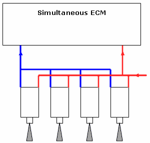
Figure 1.0
The voltage at the injector is present only when the engine is cranking or running, because the voltage supply is controlled by a tachometric relay.
The injector is supplied with fuel from a common fuel rail. The length of time for which the injector is held open depends on the input signals seen by the engine management ECM from its various engine sensors. These input signals will include:
- The resistance of the coolant temperature
- The output voltage from the airflow meter (when fitted)
- The resistance of the air temperature sensor
- The signal from the Manifold Absolute Pressure (MAP) sensor (when fitted)
- The position of the throttle switch / potentiometer
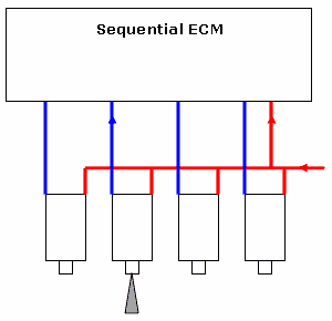
Figure 1.1
The held open time or injector duration varies to compensate for cold engine starting and warm-up periods, a large duration decreasing the injection time as the engine warms to operating temperature. The duration also expands under acceleration and contracts under light load conditions.
Depending on the system encountered, the injectors can fire either once or twice per cycle. With simultaneous injection the injectors are wired in parallel and all fire together at the same time (Fig 1.0).
Sequential injection, as with simultaneous, has a common supply to each injector, but unlike simultaneous, has a separate earth path for each injector (Fig 1.1). This individual firing allows the system, when used in conjunction with a phase sensor, to deliver the fuel when the inlet valve is open and the incoming air helps to atomise the fuel.
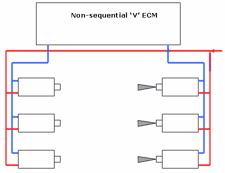
Figure 1.2
It is also common for injectors to be fired in 'banks' on 'V' configuration engines (Fig1.2). The fuel is delivered to each bank alternately. In the case of a Jaguar V12 the injectors are fired in 4 groups of 3 injectors.
Because of the frequency of the firing of the injectors, a sequential injector normally has twice the duration, or opening time, of a simultaneous pulse. This is, however, determined by the injector's flow rate and the fuel's operating pressure.
In the waveform illustrated below (Fig 1.3) we can observe the current drawn by the injector (shown in red) at the same time as monitoring the primary ignition trace (shown in blue). The main reason for evaluating these two waveforms together is to identify the cause of a non-start situation or a sudden loss of power causing the engine to stop. If the primary trace is absent, there will be no switching of the injectors as these two circuits are timed together while the loss of the injector current signifies that a fault has occurred within the injection circuit.
The frequency of the injection trace when compared to the primary signal differs between sequential and simultaneous injection. Sequential has one pulse per 720°, while simultaneous will usually has two. Some simultaneous systems do, however, have a single pulse, but these are in the minority.
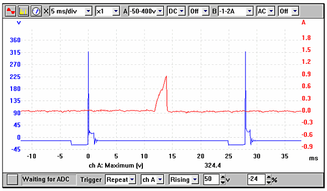
Figure 1.3
Engine Sensors
The following sections detail the inputs to the vehicle's ECM that contribute towards the desired injector duration. While certain components may not be fitted on some systems, the text endeavors to cover all variants.
Coolant Temperature Sensor
The coolant temperature sensor is a small two-connection device that reports the engine's temperature back to the ECM. It is this signal that determines the engine's warm-up enrichment and its fast idle speed.
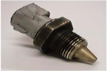
Figure 1.4
This sensor normally has a Negative Temperature Coefficient (NTC), which means that the component's resistance reduces as the temperature increases. A Positive Temperature Coefficient (PTC) sensor is not as common as the NTC and its resistance reacts to temperature in the opposite way.
To increase the vehicle's driveability and performance on pre 1992 non-cat cars, the resistance can be altered by calculating and inserting a resistor in series with the coolant temperature sensor, however, this resistance has to be calculated before its insertion. The resistor should not be inserted in series when the CTS is an NTC device. It should also be noted that the resistor should not be placed in parallel, as this will reduce the overall resistance. This modification cannot, however, be implemented on engines equipped with a catalytic converter as this extra fuelling will upset the corrective nature of the lambda or oxygen sensor.
The sensors are manufacturer-specific and the outputs vary dramatically although the sensors may look identical. Any poor connections on this circuit will introduce an extra resistance in series and will falsify the readings that the ECM sees — reading the resistance at the ECM multi-plug will confirm this.
Fig 1.4 illustrates Ford's version of a coolant temperature sensor.

Figure 1.5
The Coolant Temperature Sensor (CTS) is invariably be a two-wire device with a voltage supply of approximately 5 volts.
The sensor itself has the ability to alter its resistance with engine temperature change. The majority of sensors have a Negative Temperature Coefficient (NTC), which results in the resistance of the component decreasing as the temperature increases. The resistance change therefore alters the voltage seen at the sensor and can be monitored for any discrepancies across its operational range.
Select a time scale of 500 seconds, then connect the oscilloscope to the sensor and observe the output voltage.
Start the engine and in the majority of cases the voltage will start in the region of 3 to 4 volts, but will depend on the temperature of the engine; as the temperature increases the resistance decreases and the voltage will also be seen to drop. See Fig 1.5.
The rate of voltage change is usually linear with no sudden changes to the voltage. If the CTS displays a fault at a certain temperature, this is the only true way of detecting it.
Vauxhall CTS

Figure 1.6
The CTS used in the Multec system on the Vauxhall Vectra 1.6 Lt. engine has a distinctive waveform when viewed on the oscilloscope. The voltage seen at the CTS will display a conventional voltage reduction until the engine reaches 40 - 50 °C, at which point the voltage rises dramatically due to internal switching inside the Electronic Control Module (ECM). This is illustrated in Fig 1.6. The reason for the voltage change is that at higher operating temperatures (50 °C plus), the ECM increases the sensor voltage in order to gain finer control.
All the example waveforms used were recorded using a Pico automotive oscilloscope. Other manufacturers' equipment will have different voltage ranges but the resultant picture should be very similar. Please remember that using a higher voltage range will result in the waveform appearing to have a lower amplitude, although the overall voltage will be the same.
In the next tutorial we will continue looking at the other sensors whose inputs affect the injector duration.
This tutorial was first published by The Institute of the Motor Industry .
|