


In this tutorial we will conclude trigger signals, taking a final look at BMW coil per cylinder multi-pulsed primary's and begin to look at the relationship between the crank angle sensor and the camshaft sensor.
BMW Coil per Cylinder
In Fig 1.0 it can clearly be seen that the primary circuit is subjected to multiple triggering. This function only occurs at idle and is present to stop any fouling of the spark plugs and provides a cleaner burn, thus reducing hydrocarbon emissions. The primary reverts back to conventional switching when the accelerator pedal is touched and the Electronic Control Module (ECM) sees an increase in voltage from the throttles potentiometer, as shown in Fig 1.1.
The extended spark duration time (in this case 6.7 milliseconds) can be monitored by probing the switched earth return on the individual coils using a voltage probe. When the coil saturation time between each pulse is monitored, it can be seen that there is only approximately 0.75 of a millisecond to produce the required voltage. This is a real testament to the electronics fitted within the system. The multi-pulsing is a unique way of burning the excess of hydrocarbons still within the combustion chamber when the engine has a large amount of 'valve overlap' — common with high performance engines.
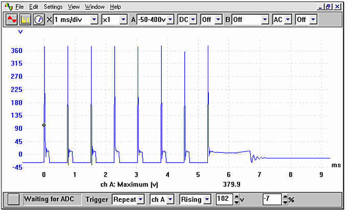
Figure 1.0
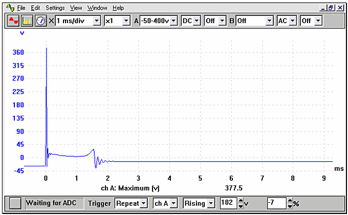
Figure 1.1
Camshaft Sensors
This sensor can also be referred to as the Cylinder Identification (CID) sensor. As the engine rotates the sensor will signal to the Electronic Control Module (ECM) that the engine is approaching number 1 and the timing of the injection pulse can be determined. On an inductive sensor, a resistance value should be seen between its terminals with these terminating back at ECM. The output signal from these units can be in either analogue or digital format (sine wave or square wave) and will depend on the manufacturer concerned. Vauxhall have also used an Alternating Current (AC) excited sensor on their Simtec engine management system, which is described later in this section.
It is unlikely that a failed camshaft position sensor will cause the engine not to start, as this particular sensor only times the injector pulses. When this sensor is disconnected the point at which the injector fires can be seen to 'shift' giving an incorrect point at which the fuel is delivered behind the inlet valve.
Camshaft Sensors: Inductive
This particular type of sensor generates its own signal and therefore does not require a voltage supply to power it. This particular style of sensor is recognisable by its two electrical connections, with the occasional addition of a coaxial shielding wire to reflect any HT signals that may corrupt the signal.
The voltage produced by the camshaft sensor will be determined by several factors, these being the engine's speed, the proximity of the metal rotor to the pick-up and the strength of the magnetic field offered by the sensor. The ECM needs to see the signal when the engine is started for its reference; if absent it can alter the point at which the fuel is injected. The driver of the vehicle may not be aware that the vehicle has a problem if the CID sensor fails, as the drivability may not be affected.
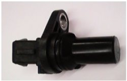
Figure 1.2
The characteristics of a good inductive camshaft sensor waveform is a sinewave that increases in magnitude as the engine speed is increased and usually provides one signal per 720° of crankshaft rotation (360° of camshaft rotation). The voltage will be approx 0.5 volts peak to peak while the engine is cranking, rising to around 2.5 volts peak to peak at idle as seen in the example show in Fig 1.3. This voltage may differ between different manufacturers, requiring the appropriate data to be sourced. An example of an inductive camshaft sensor is shown in Fig 1.2.
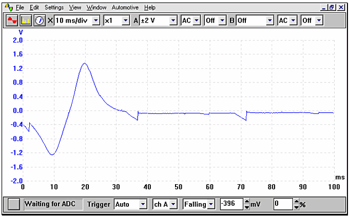
Figure 1.3
Camshaft Sensors: Hall Effect
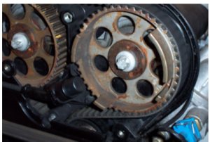
Figure 1.4
The characteristics of a good Hall Effect waveform are clean, sharp switching and as with all other Hall units has 3 electrical connections.
Unlike the output picture from a Hall Effect distributor output, the 'spacing' of the squarewaves will be unequal; this enables the vehicles ECM to determine the camshafts position. In Fig 1.4 we can see the location of the camshaft sensor and the targets that provide the squarewave output. This particular example is taken from a Vauxhall Vectra fitted with the Ecotec engine.
In Fig 1.5 we can see the relationship between the targets and the generated output signal.
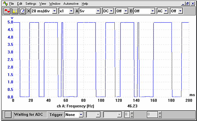
Figure 1.5
Vauxhall Ecotec AC Excited
This camshaft sensor differs in operation from the other sensors by having an Alternating Current (AC) voltage supply to the CID sensor. The ECM supplies a very high frequency at around 150 KHz (2500 cycles per second) to an exciter coil that is located in close proximity to a rotating disc. The disc is located at the end of the camshaft and has a section removed that when 'open' allows the frequency to excite the receptor (through mutual inductance) and returns the signal to the ECM, indicating the position of number 1 cylinder. Fig 1.6 shows typical outputs.
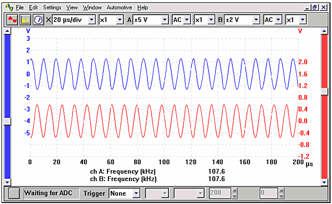
Figure 1.6
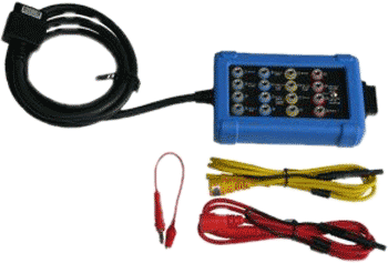
All the example waveforms used were recorded using an automotive oscilloscope loaned by Pico . Other manufacturers' equipment will have different voltage ranges but the resultant picture should be very similar. Please remember that using a higher voltage range will result in the waveform appearing to have a lower amplitude, although the overall voltage will be the same.