


Following on from last month's topic, we continue to look at the signals that determine, when processed, the point of ignition.
In this months topic we will conclude the popular crank angle sensors by looking at the Vauxhall Multec, Hall effect crank angle sensors and the Ford DIS systems. We will also be looking at the co-relationship between the sensors and the primary picture.
Vauxhall ECO TEC 1.6 Lt. Multec
The double-ended coil in this particular case differs from many other systems as it has the ignition amplifier built into the coil pack. The coil/amplifier pack will have 4 electrical connections: the pack receives a 12 Volt supply from the ignition switch, has an independent earth return and the remaining two connections are in the form of a 5 Volt 'squarewave' signal from the Electronic Control Module.
The ECM receives information from the engine's sensors and calculates the point of ignition by the ECM from its internal pre-set parameter. At the designated point, the 5-volt supply drops to zero volts, signalling the amplifier to remove the earth path on the coil primary, firing the coil. The coil/amplifier pack has two separate sides, one for cylinders 1 4 and the other for cylinders 2 3. Using an oscilloscope with a dual trace facility, both circuits can be monitored It can then be seen that the coils are fired alternately, as the example shows in Fig 1.0.
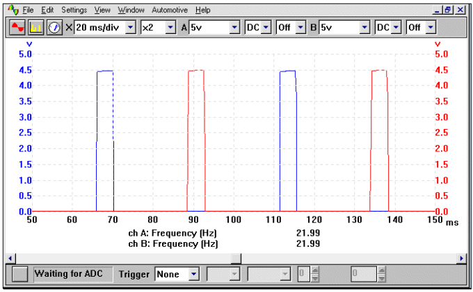
Figure 1.0
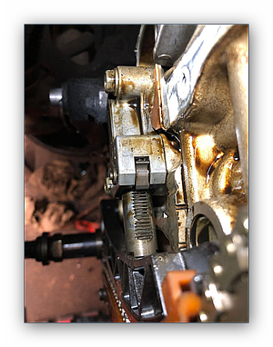
While the position of the crank angle sensor is at the bottom of the engine and does not allow easy access, there is a multi-plug connection located adjacent to the airflow meter, shown in Fig 1.2.
The inductive sensor is normally a two-wire device, however there are three wires in this particular instance. The third wire is from the coaxial braid used to keep out any HT interference that may interrupt or corrupt the signal seen by the ECM.
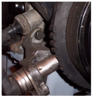
Figure 1.1
The Multec system employs a conventional inductive crank angle sensor that is located adjacent to the front pulley. This can be seen in Fig 1.1, where both the sensor and the reluctor's teeth are clearly visible.
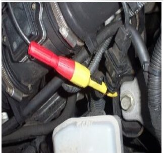
Figure 1.2
In the above illustration, we can see how the relationship between the teeth and the spacing of the waveform relate. While this waveform represents the correct cranking speed output from this particular system (Fig 1.3), there will be slight variations between different motor manufacturers.
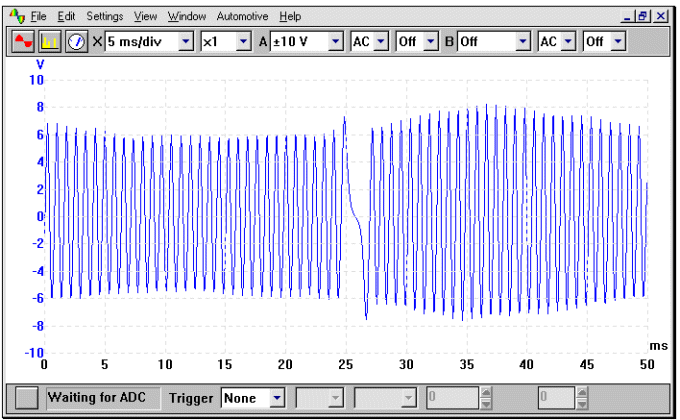
Figure 1.3
Hall Effect Crank Angle Sensors
This system is used on certain Vauxhall Vectra 2.0 Lt. fitted with a Simtec 56.5 engine management system, and is the vehicle used in the example waveforms. This system should not however be confused with the Simtec system which uses a frequency modulated signal (AC excited).
The crank angle sensor in this particular instance is located adjacent to the front pulley onto which the 'trigger targets' are spaced. The output signal produced is then used by the engine control module to determine the exact position of the engine.
The Hall effect type crankshaft sensor is a simple digital 'on / off' switch which produces a digital output that is recognised and processed by the ECM. The sensor is trigged by the rotating metal targets, which pass in close proximity to the sensor. This results in the characteristic squarewave output.
The sensor will have the usual Hall effect three electrical connections, a live supply, an earth and the output signal. The square wave when monitored on an oscilloscope may vary slightly in amplitude; this is not critical as it's the frequency that;s important. In Fig 1.4, we can see how the relationship between the targets and the spacing of the waveform relate.

Figure 1.4
Ford DIS systems
The EDIS module fitted to the distributorless range of Ford vehicles, works in conjunction with the main EEC IV ECM. Its function is to collect the signal from the crank angle sensor, modify the signal from its original Analogue Current (AC) signal into a digital square wave. This signal is known as the Profile Ignition Pick-up (PIP) signal. The PIP signal notifies the ECM as to the exact position of the engine and this signal is then further modified into the Spark Advance Word (SAW) signal, modified to accommodate any timing advance that the ECM sees necessary. The advance figure will be determined by the engines speed and the engine load. The returning SAW signal to the EDIS unit will determine when the earth return circuit is released from the coil negative, in order for the coils to be fired. As there is only one SAW signal that triggers the coil for cylinders 1 & 4, the point of ignition is calculated by the EDIS unit for cylinders 2 & 3.
As with all double-ended coil configurations, the system operates a wasted spark policy, which will fire the plugs even if they are on the exhaust stroke.
Both signals can be seen in the example waveform Fig 1.5, with the PIP signal in blue and the SAW signal in red.
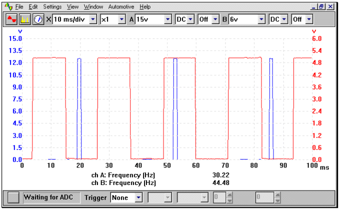
Figure 1.5
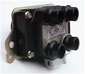
Figure 1.6
Fig 1.6 shows a typical 4 cylinder Ford DIS coil pack.
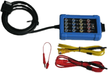
All the example waveforms used were recorded using an automotive oscilloscope loaned by Pico . Other manufacturers' equipment will have different voltage ranges but the resultant picture should be very similar. Please remember that using a higher voltage range will result in the waveform appearing to have a lower amplitude, although the overall voltage will be the same.
Please remember that using a higher voltage range on the oscilloscope will result in the waveform appearing to have a lower amplitude, although the overall voltage will be the same.