


The vehicle had an intermittent misfire and the engine MIL was on. I found the engine misfiring constantly, with excessive smoke issuing from the tailpipe, so I left it running for a little while to get a feel of the problem and to scan the system for trouble codes. I couldn’t keep the engine running for too long because the hydrocarbon (HC) content in the smoke was unbearable. It was immediately clear that this wasn’t a normal misfire, and there were a few causes for concern:
- Suppose we were dealing with an ignition misfire that let raw fuel pass in and out of the combustion chamber. We would expect to see large amounts of HC in the exhaust stream, but that fault seems too extreme to explain our symptoms.
- The car was a 2004 model and so came under Euro 3 emission regulations. Just one of the ways to reduce unnecessary harmful emissions is through “Misfire Monitoring”. When a misfire for whatever reason is detected, which in most cases causes unburnt hydrocarbons to be emitted, the Engine Control Module normally intervenes and cuts fuel to that cylinder. With this problem car, we had a clear misfire and still large amounts of unburnt fuel being emitted. Could this be a clue?
The scan tool showed only one diagnostic trouble code (DTC) logged — P0201 INJECTOR CIRCUIT MALFUNCTION CYL NO.1
This type of code is a big help because it’s specific to a component and is directly related to an electrical problem. The dreaded codes are P030#, which relate to general engine misfires, but I could list probably 20 different reasons that will cause a misfire and these DTCs to become logged, so this is not much of a help. Also, we only have one DTC logged, which is another clue. Several attempts to erase the DTC failed, with the code and the engine MIL coming straight back on. So we know the fault is permanent, we know the offending cylinder, and more importantly we know the offending circuit.
It’s time to hook up the scope.
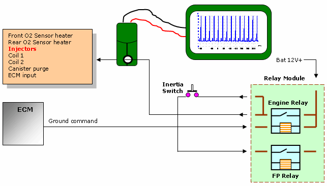
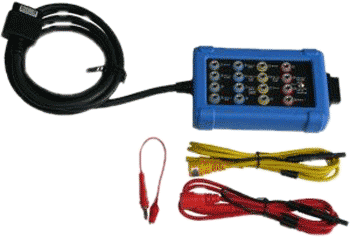
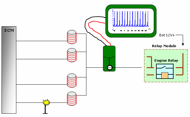
Here we have the scope and low-amp clamp measuring current drawn from the main 12V output from the relay module to various engine components. In this case we are interested only in No.1 injector circuit, but from this test location we could build a bigger picture of the fault by including all injectors.
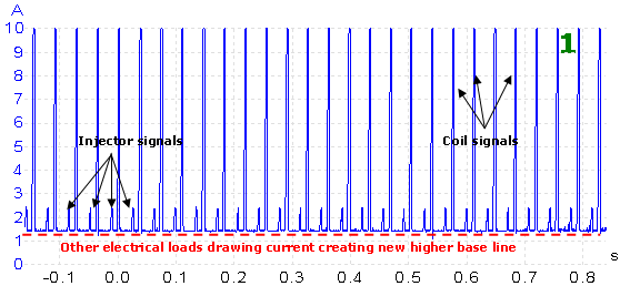
Capture 1 shows a collection of electrical loads that this particular 12V source is supplying. Unfortunately, whilst I was gaining access to the relevant cabling and connecting the scope, the fault went away and the engine started firing again on all four cylinders. This was a big clue. When connecting a scope, some cable and connector flexing is inevitable, so it must have been this that disturbed the fault. The capture showed typically good signals, with all injectors firing and coil signals to match. But which one is our No.1 injector? Well, this capture offers no indication which is which, but we can deduce that no abnormal activity exists.
Each signal trace was examined for general integrity, and no abnormality or inconsistency was noted. This is just what you would expect from a sound running engine.
Only one of the scope’s channels was used, leaving an option to synchronize the current trace with a known firing command. The obvious choice would be to view our suspect No.1 injector negative line. I chose not to use the No.1 injector ground command as a sync, for fear of losing the fault completely due to flexing of the cable and connector. I felt confident that the fault was severe enough to be spotted through the current clamp in one form or another.
Because we suspected that a cable flex affected the fault, the entire engine bay wiring harness was subjected to a “wiggle” test in attempt to flush out the fault. When using this technique, always start out very gently. Wiring harnesses throughout the car are all subjected to driving vibrations and knocks, very often just around one particular point.
It’s here where your fault is most likely to be, so it’s no good yanking and pulling on the harness, because the fault you are investigating didn’t have to be yanked or pulled in the first place for it to become a problem.
It didn’t take long before the engine stumbled and kicked out smoke. Capture 3 shows the result.
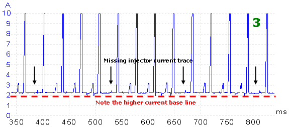
We see a missing injector current trace which has to be our No.1 injector. A missing current trace indicates that injector isn’t working, but this makes it hard to explain the massive HC level at the tailpipe. The capture also shows the minimum current from capture 1 at 1.4 A raised here to 2.3 A; a difference of 0.9 A. Can this be a coincidence?
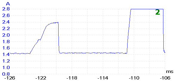
This is an excerpt from capture 1 showing known good injector traces. This one has been zoomed in slightly to get a better look. Each injector is seen to saturate at approx. 0.937 A.
This fits nicely with the injector winding resistance and engine running supply voltage.
Charging voltage 14 V
Injector resistance 15 Ω
Current draw 0.93 A
The facts so far are all pointing to a short to ground in the switched negative supply line to No.1 injector.
- The PCM will recognize this as a circuit fault and log the DTC.
- The current base line is increased because No.1 injector is drawing its saturated current level of 0.9 A
- With the injector negative cable shorted permanently to ground, that cylinder will now receive constant fuel flow irrespective of correct timing control. The ignition spark doesn’t stand a chance of igniting this mixture, which explains the misfire and extreme HC gas content.
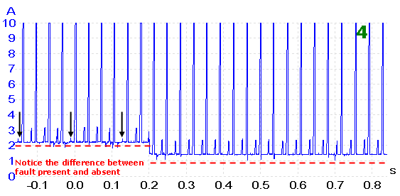
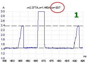
In Capture 4 we see the distinct difference between fault present and fault absent.
Finding our short to ground turned out to be easy. Each segment of wiring harness between ECM and injector was carefully flexed until one area stood out as being strongly related to the fault. I could get the fault to appear at will as if flicking a switch.
For this part of the investigation I only needed the ignition on, and I could hear the injector working as I flexed the harness.
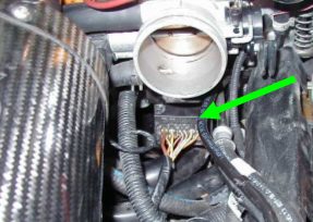
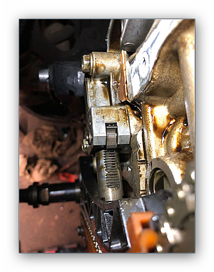
This photo shows one part of the engine harness which runs to a block connector under the throttle housing and carries all injector and relevant cabling. When this connector block was gently moved, our fault would appear.
I switched off the ignition and disconnected the block connector for a closer look. All terminals seemed OK and well secured. A problem inside the connector housing didn’t fit the fault; this might perhaps cause an open circuit condition where the terminals don’t quite meet, but not our condition where we are looking for a short to ground.
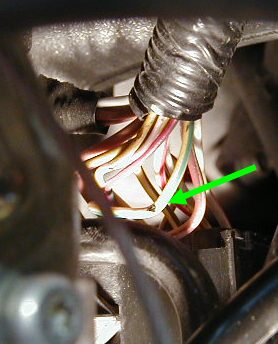
I traced the problem to just the other side of the connector block. The negative command line to No.1 injector had chafed on the underside of the throttle housing. Incidentally, you can also see in the picture where the original harness protective tubing starts; the short length of unprotected wiring from the connector to the tubing was enough to allow the cable to stray and chafe.
None of the cable strands had been damaged, so I simply had to re-insulate and reposition the cabling.
This had been an intermittent problem for the customer for some time, and as a result the engine oil had suffered by being saturated with raw unused fuel. When the vehicle was taken for a run to settle things down, the fuel trim was up into double figures trying to back off the injection duration. The crankcase ventilation was channeling the HC held in the oil back into the inlet plenum.
To put a final touch on the car, I replaced its oil and filter.