| By Auto Solve
Welcome to the Pico Fuel Injection Tutorial where we will be looking at the Electronic Fuel Injection system, with particular focus upon the sensors and actuators, their resultant inputs and outputs, to and from the vehicle's ECM. The tutorial looks at the multi-point injection system, with single-point being covered in a later tutorial.
Overview
Both the multi-point and the single-point systems operate in a very similar fashion having an electro-mechanically operated injector/injectors opening for a predetermined length of time. The amount of injection period is determined by the engine's Electronic Control Module (ECM). This time period will depend upon the engine's temperature, the engine load and the information from the lambda sensor. The fuel is delivered from the tank, via a filter and a regulator determines its operating pressure. The fuel is delivered to the engine in a precise quantity and in most cases is injected into the inlet manifold awaiting the valve's opening, therefore being drawn into the combustion chamber by the incoming air.
The Fuel Tank
This is the obvious place to start in any full system explanation. Unlike the tanks on early carburettor equipped vehicles, it is a sealed unit that allows the natural gassing of the fuel to aid delivery to the pump by slightly pressurising the system. It may be noted that when the filler cap is removed, pressure is heard to escape. The fuel filler caps are no longer vented.
The Fuel Pump
This type of high pressure fuel pump (Fig 1.0) is denoted as a roller cell pump, with the fuel entering the pump and being compressed by rotating cells which force it through the pump at a high pressure. The pump is capable of producing a pressure of 8 bar (120 psi) with a delivery rating of approximately 4 to 5 litres per minute. Within the pump is a pressure relief valve that lifts off its seat at 8 bar to arrest the pressure if a blockage in the filter or fuel lines or other eventualities cause it to become obstructed. The other end of the pump (output) is home to a non-return valve which, when the voltage to the pump is removed, closes the return to the tank and maintains pressure within the system. The normal operating pressure within this system is approximately 2 bar (30 psi) and at this pressure the current draw on the pump is 3 to 5 amps. Fuel passing across the fuel pump's armature will be subjected to sparks and arcing; this on the surface appears quite dangerous, but the absence of oxygen means that there will not be an explosion!
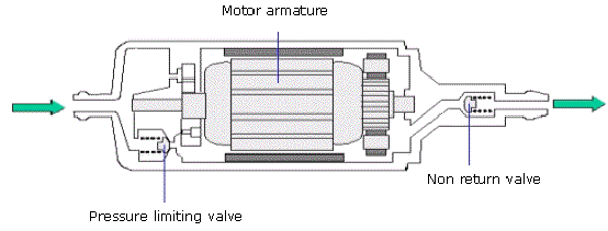
Figure 1.0
The majority of fuel pumps fitted to today's motor vehicles are fitted within the vehicle's petrol tank and are referred to as 'submerged' fuel pumps. The pump will invariably be located with the fuel sender unit and both units can sometimes be accessed through an inspection hole either in the boot floor or under the rear seat. Mounted vertically, the pump comprises an inner and outer gear assembly that are termed as the 'gerotor'. The combined assembly is secured in the tank using a series of screws and sealed with a rubber gasket, or with a bayonet type locking ring. On some models, there are two fuel pumps, the submerged pump acting as a 'lift' pump to the external roller cell pump.
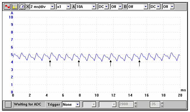
Figure 1.1
The waveform illustrated in Fig 1.1, shows the current for each individual sector of the commutator. The majority of fuel pumps will have 6 to 8 sectors and a repetitive point on the waveform can indicate wear and an impending failure. In the illustration waveform it can be seen that there is a lower current draw on one sector and this is repeated when the pump has rotated through 720°. This example has 8 sectors per rotation.
Fig 1.2 shows typical current draw access to the fuel submerged pump.
The current drawn by the fuel pump is dependent upon the fuel pressure but should be no more than 8 amps found on the Bosch K-Jetronic mechanical fuel injection, which has a system pressure of 75 psi.
Fuel Supply
A conventional 'flow and return' system has a supply of fuel delivered to the fuel rail and the unwanted fuel is passed through the pressure regulator, back to the tank. It is the restriction in the fuel line created by the pressure regulator that provides the system operational pressure.
Returnless Fuel Systems
Have been adopted by several motor manufacturers and differ from the conventional by having a delivery pipe only to the fuel rail with no return flow back to the tank.
The returnless systems, both the mechanical and the electronic versions, are instigated by emissions protocol. The absence of heated petrol returning to the fuel tank reduces the amount of evaporative emissions, while the fuel lines are minimised, thus reducing build costs.
Mechanical Returnless Fuel Systems
The 'returnless' system differs from the norm by having the pressure regulator situated within the fuel tank. When the fuel pump is activated, fuel flows into the system until the required pressure is obtained; at this point 'excess' fuel is bled past the pressure regulator and back into the tank.
The 'flow and return' system has a vacuum supply to the pressure regulator: this enables the fuel pressure to be increased whenever the manifold vacuum drops, providing fuel enrichment under acceleration.
The 'returnless' system has no mechanical compensation that effects the fuel pressure, and it will remain at a higher than usual 44 to 50 psi. By increasing the delivery pressure, the ECM (Electronic Control Module) can alter the injection duration to give the precise delivery, regardless of the engine load without fuel pressure compensation.
Electronic Returnless Fuel Systems
This version has all the required components fitted within the one unit of the submersible fuel pump. It contains a small particle filter (in addition to the strainer), pump, electronic pressure regulator, fuel level sensor and a sound isolation system. The electronic pressure regulator allows the pressure to be increased under acceleration conditions; additionally the pump's output can be adjusted to suit the engine's fuel demand. This will prolong the pump's 'life' as it is no longer providing a larger than required output delivery.
The Electronic Control Module (ECM) supplies the required pressure information, while the fuel pump's output signal is supplied in the form of a digital squarewave. Altering the squarewave's duty cycle will effect the pump's delivery output.
To facilitate the changing viscosity of the fuel with changing fuel temperatures a fuel rail temperature sensor is installed. A pulsation damper may also be fitted prior to, or within the fuel rail.
Injectors
The injector is an electromechanical device, which is fed by a 12 volt supply from either the fuel injection relay or from the ECM. The voltage will only be present when the engine is cranking or running, due to the voltage supply being controlled by a tachometric relay. The injector is supplied with fuel from a common fuel rail. The length of time the injector is held open will depend on the input signals seen by the ECM from its various engine sensors. The held open time or 'injector duration' will vary to compensate for cold engine starting and warm-up periods, i.e. a large duration that decreases the injection time as the engine warms to operating temperature. The duration time will also expand under acceleration and contract under light load conditions.
The injector will have a constant voltage supply while the engine is running and the earth path will be switched via the ECM. An example of a typical waveform is shown below in Fig 1.3.
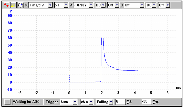
Figure 1.3
Multi-point injection may be either sequential or simultaneous. A simultaneous system will fire all 4 injectors at the same time with each cylinder receiving 2 injection pulses per cycle (720° crankshaft rotation). A sequential system will receive just 1 injection pulse per cycle; this is timed to coincide with the opening of the inlet valve. As a very rough guide the injector durations for an engine at normal operating temperature, at idle speed are around 2.5 ms for simultaneous and 3.5 ms for sequential.
Anything electro-mechanical will of course take a small amount of time to react, as it will require a level of magnetism to build before the pintle is lifted off its seat. This time is called the 'solenoid reaction time'. This delay is important to monitor and can sometimes equate to a third of the injector's total duration. A good example of the delay in opening can be seen in the example waveform shown below in Fig 1.4.
It can be clearly seen from the example waveform that the waveform is clearly 'split' into two easily defined areas. The first part of the waveform is responsible for the electromagnetic force lifting the pintle, in this example the time taken is approximately 0.6 ms. At this point the current can be seen to fall before rising again as the pintle is held open. With this in mind it can be seen that the amount of time that the injector is held open is not necessarily the same as the time measured. It is not however possible to calculate the time taken for the injectors spring to fully close the injector and cut off the fuel flow.
This test is ideal for identifying an injector with an unacceptably slow solenoid reaction time. Such an injector would not deliver the required amount of fuel and the cylinder in question would run lean.
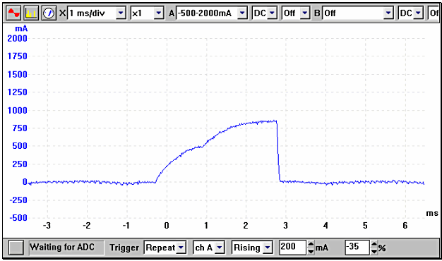
Figure 1.4
Fig 1.5 shows both the injector voltage and current displayed simultaneously.
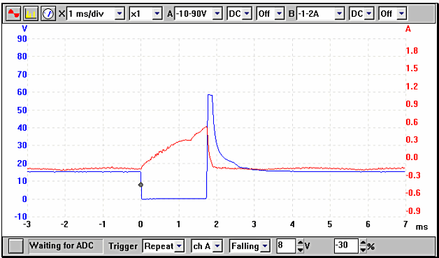
Figure 1.5
All the example waveforms used were recorded using a Pico automotive oscilloscope . Other manufacturers' equipment will have different voltage ranges but the resultant picture should be very similar. Please remember that using a higher voltage range will result in the waveform appearing to have a lower amplitude, although the overall voltage will be the same.
In the next tutorial we will be look at the input signals to the ECM that control the injector duration.
This tutorial was first published by The Institute of the Motor Industry .
|